Tired of software, longing for the touch and feel of circuits, I’ve been looking for something to satiate my sonic hunger. And, I wanted to get my hands dirty. So, I placed a small order of electronic parts with mouser.com. Additionally, ever since having discovered that the cigar store in Staunton, VA sells nice wooden cigar boxes between $3 and $5 (size and quality), I’ve been itching to put a nice piece of analog circuitry inside.
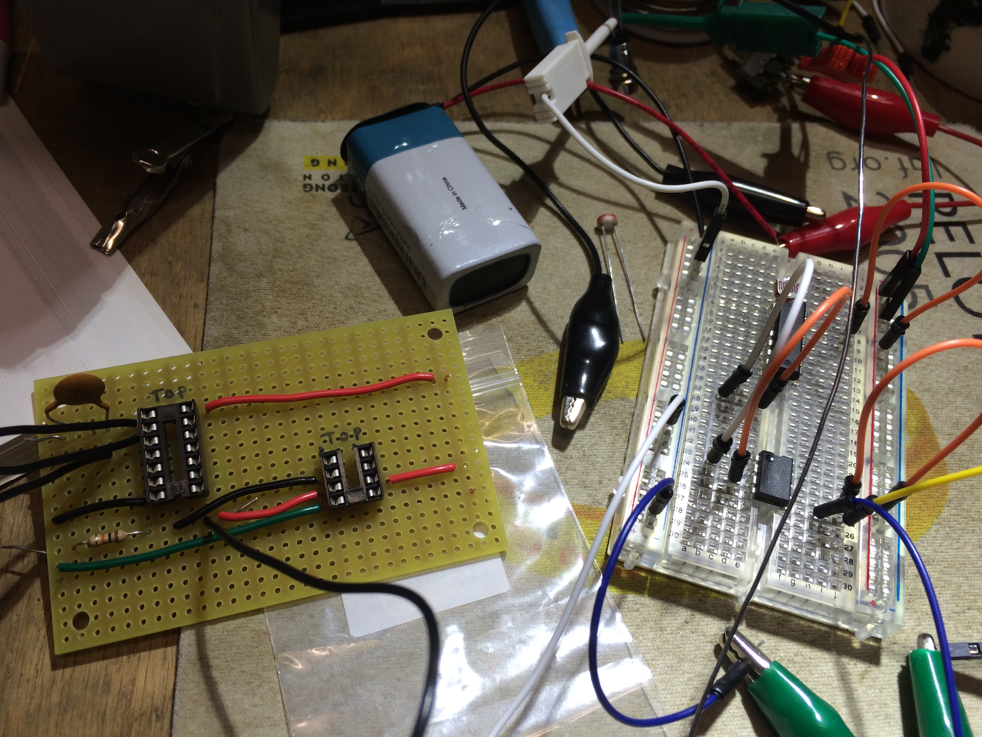
Thanks to Nic Collins (Handmade Electronic Music: The Art of Hardware Hacking![]() p.161), I found a nice schematic on controlling pitch and volume with photo-resistors. (note: instead of throwing up the schematic as an image, I have posted a pic of my breadboard circuit based upon his schematic below. Regardless, I urge you to support Nic by buying his book. It’s really good).
p.161), I found a nice schematic on controlling pitch and volume with photo-resistors. (note: instead of throwing up the schematic as an image, I have posted a pic of my breadboard circuit based upon his schematic below. Regardless, I urge you to support Nic by buying his book. It’s really good).
After wiring the circuit up on a bread-board, I noticed how quiet the theremin sounded. To boost the signal, I needed an audio amplifier, so I turned to the good, old Radioshack project book, Timer Op Amp and Optoelectronic Circuits and Projects Vol. 1 (p.43).![]() Forrest Mims is completely straight-forward on schematic, use, and example.
Forrest Mims is completely straight-forward on schematic, use, and example.

Taking the output of the photo-resistor theremin into the 386 seriously boosted the audio signal, even though I did not have any 220uF capacitors (as shown above). Later, I learned from talking with University of Virginia’s Tech Director, Travis Thatcher, that the capacitor on the output signal is to remove any DC offset that could damage the speaker. A 10uF cap would work fine, or the 220uF as shown. While no capacitor worked for me on this project, I did add a 220uF cap to my parts list for next time.

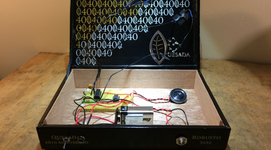
Above is the circuit. The top, 14 position IC circuit is a Hex Schmitt trigger, which is used as the oscillator. The 10k photo-resistor on positions 1 and 2 control pitch, while the other resistor controls volume (one could use a potentiometer instead of a photo-resistor for either control). The audio outs feed into the smaller, 8 position, 386 amplifier. Everything is driven on a 9V battery.
What is not shown in the breadboard schematic above are three simple, but useful additions. I added an on/off switch for power, a LED indicator light, and a mono audio jack output for sending the signal to an amplifier (e.g. guitar amp). Since this was my first project using a power switch, I scoured the internet on wiring and definitions. I learned a lot from this SparkFun article on switches.
While the breadboard took less than ten minutes, the soldering transfer took a few hours… yes, I am slow. “Measure twice, cut once”, thank you Grandpa Overholt. Methodical work can have its benefits, however (no re-soldering on this job!). After completing the circuit board, I set the board on stand-offs in the cigar box.
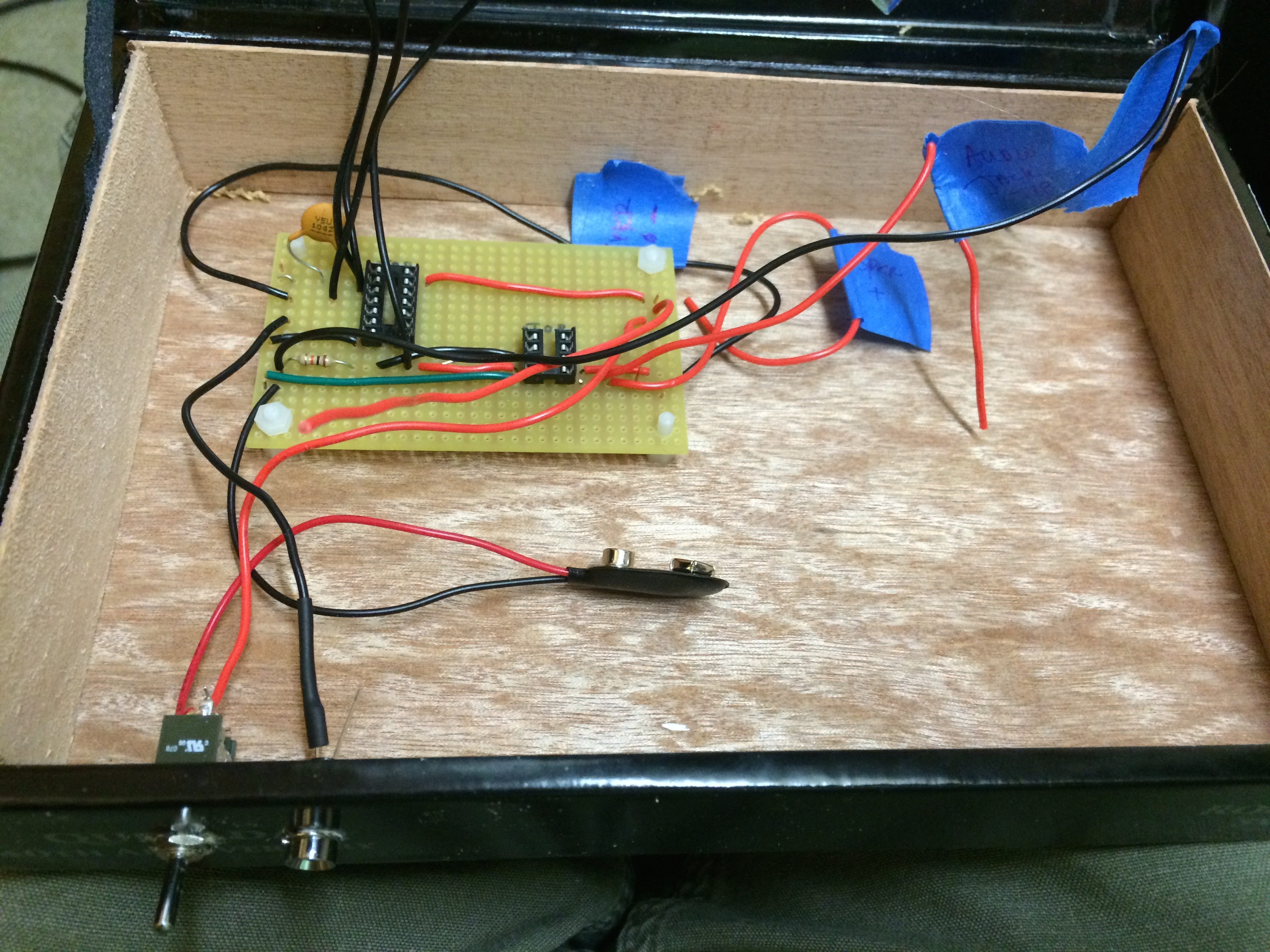
With the parts that I ordered, I found I had little clearance on my connectors. I had to remove the front piece of wood in the cigar box so my washers would tighten up on all the connectors (switch, LED, and audio jack). While soldering, I also found my heat sink![]() to be a great tool, especially while working on the LED and photoresistors (I was concerned about damage due to heat transfer from both the soldering iron and the heat shrink gun).
to be a great tool, especially while working on the LED and photoresistors (I was concerned about damage due to heat transfer from both the soldering iron and the heat shrink gun).
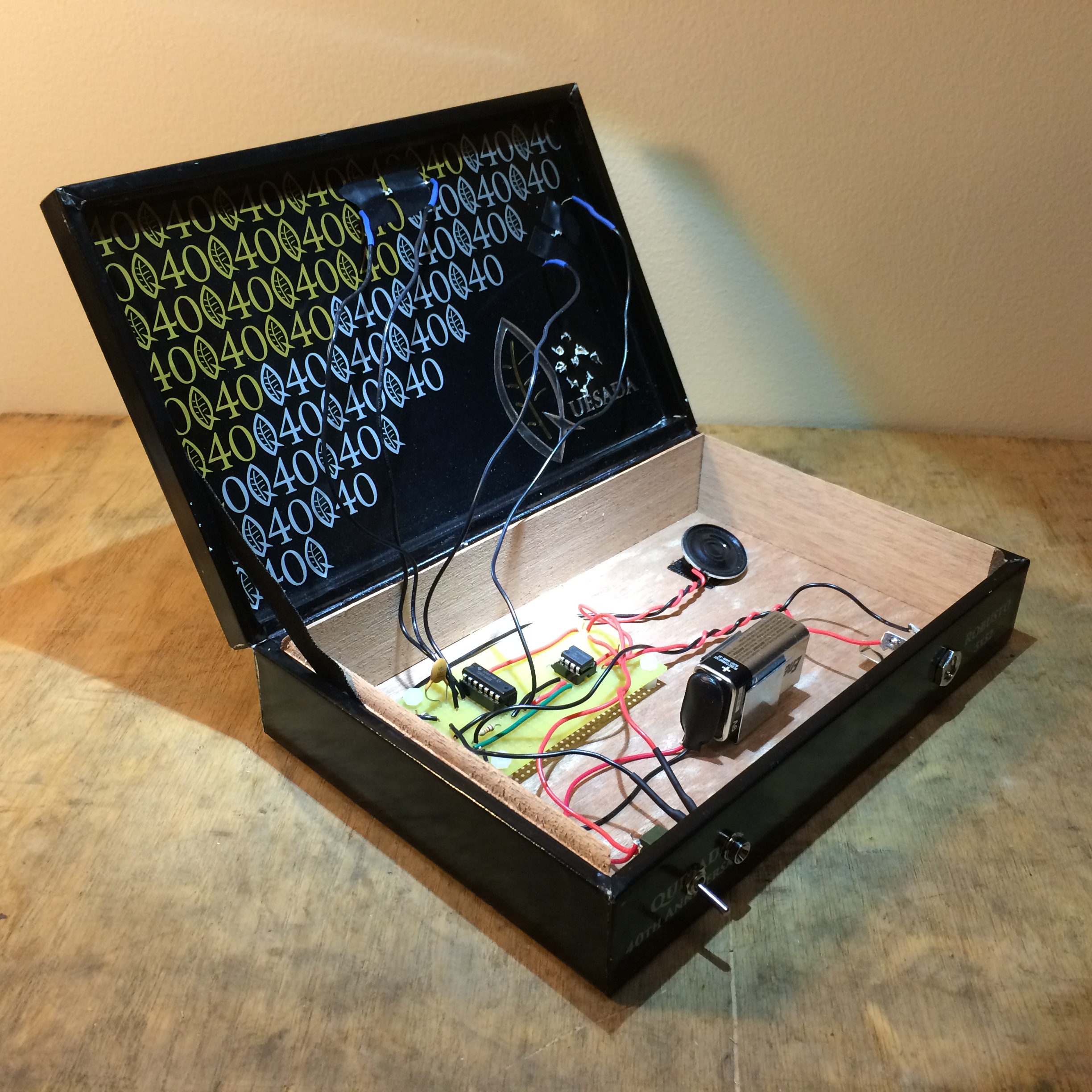
I drilled small 1/16″ holes to stick the photo-resistors through, bent the leads, and used electrical tape on the back to help support. I also drilled holes above the speaker, although this box design utilizes the speaker as a monitor and not as the main audio output. I used a small piece of velcro to affix the mylar speaker to the cigar box.
In the end, I was pretty happy with the product and the sound. If I had to redo, which is certainly possible for me to make another, I would include a volume knob (10k variable resistor), as the audio amplifier is almost too good! My guitar amplifier is set at near 0 currently (0.0001?), and I can turn up the amp (to 1.1, not necessarily 11, but sounds like it), if I run my signal through a compressor (e.g. MXR M102 Dyna Comp![]() ).
).
I would additionally add a resistor on the LED, so it won’t burn out. My LED burnt out after two days, and I found a good article on Adafruit explaining why. All I needed was to add a simple 250ohm resistor on the negative lead. Both of these items (10k pot and 250ohm resistor) are included on my parts list, for anyone wanting to cook one up.
Article Reference:
Photoresistor Theremin Parts (on mouser.com)